Stepper Motor Driver
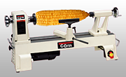
I'm currently using a Gecko G540 drive module to drive the stepper motors. This module has the ability to drive up to 4 stepper motors. They label the connections as XYZA -- we'll connect the C-axis stepper to the A output and leave the Y output unconnected.
Gecko provides a wealth of technical information about stepper motors in general and their products in particular. Take the time to download their information, read it, and understand it.
There are some nice things about this driver. It has the ability to provide 10 micro-steps for every full step of the motor, thus increasing the smoothness of cuts by 10X. It also has an adjustment to smooth the motion of the motor at slow speeds. This works particularly well because we tend to use the motors in this slow range where smoothness is important.
There are some things that I don't like about the G540:
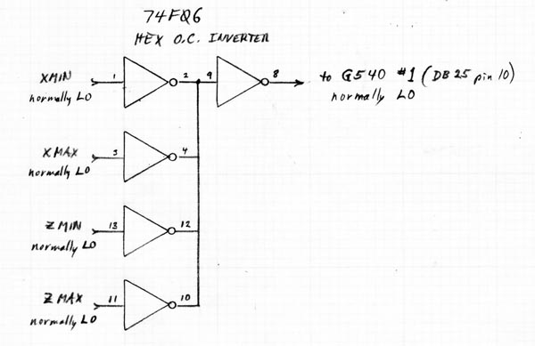
- Their spec sheet says the inputs (for connection to the limit switches) are 5-volt (TTL) compatible. This is incorrect! The G540 tries to pull the inputs up to 12 volts from an internal supply. If your limit switches are not open circuit (or open collector able to withstand a higher voltage) then you will need some additional interface circuitry (see below).
- The G540 automatically goes into a power-saving mode where it reduces the motor current by 70% whenever the motor is idle more than 2 seconds. On the one hand, this is nice to keep your motors cool. However, there is a slight "twitch" in the motor when it is suddenly switched to a lower holding current. This can leave a line in your cut work. It can easily happen when you move the cutter into the work (Z-axis, for example) and then start cutting a rosette pattern. The Z-axis won't move for a while and the G540 "helps" you by reducing the current to the Z motor. You can't turn off this option.
The G540 is giving me good results, but when I get some extra cash I'll look for a different driver.